Everything that happens in a warehouse/ factory floor needs a solid platform on which all activities are carried out. The floor not only carries the load of the entire operation but also is the base for the racking systems, equipment and the surface on which the material handling equipment and other machineries run.
An Industrial floor should have high load bearing capacity, capable enough to carry heavy weight of the storage goods for stacking and racking and be able to withstand heavy movement of material handling equipment. The floor should be tough enough to resist any impacts, abrasion, slippery, oil spills, dusting, easy to clean and highly durable.
At CONFLOORS, we understand the importance and significance of the floor in warehousing/industrial sector. While designing the floor, we consider all known load factors, MHE traffic, floor impacts, floor finishing and accordingly, choose the right materials for construction of the floor so that it can serve to most of the storage goods profiles and fulfilment of all requirements.
We use different types of reinforcement method in the floor slab constructions, all confirming to floor flatness and performance to international specification and standards. In addition to traditional rebar or mesh reinforcement, Steel Fibers, Glass Fibers and Polypropylene Fibers are also used by us for floor construction.
Steel fiber reinforced concrete floor is comparatively cheaper and technically more suitable and in turn can be installed considerably faster than floors reinforced with traditional mesh or rebar, resulting in a high-quality and cost-effective warehouse floor.
Having the right flooring in the facility ensures proper movement, stability and increases productivity. Rightly done concrete floor not only saves time and money but also reduces high recurring maintenance cost.
PROBLEM
In textile and industries with lower load Kota stone was traditionally being used. Kota is a very fine grained, siliceous calcium carbonate rock of sedimentary nature. It has certain challenges like below:
Flaking: The stone tends to flake over a period of time.
Luster: Kota lacks the luster of Marble or granite.
Small Sized Tiles: Unlike Marble and Granite, Kota is not available as large slabs, due to the brittle nature of limestone. The maximum sizes are around 75 cm x 75 cm. Heavy point loads will destroy or pull of the Kota tile.
Many joints: Unlike Marble or Granite, Kota stone flooring does not give the appearance of a seam-less flooring because Kota tiles are available only in small sized tiles. Also, there is a lot of variation in color between tiles. Lot of dust and micro-organisms accumulate in these joints.
Durability: There will be constant rework required and if not maintained the floor will need lot of tile replacement.
SOLUTION AND PROCEDURE
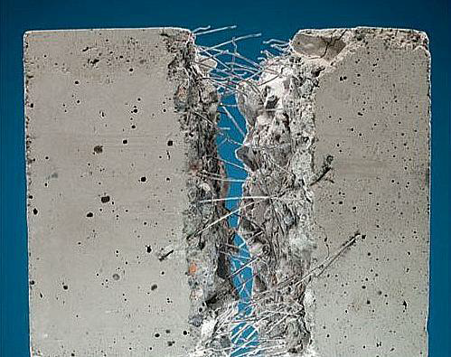
We will be laying Steel Fiber Reinforced Concrete (SFRC). The advantage is its superior resistance to cracking and crack propagation. As a result of this ability to arrest cracks, fiber composites possess increased extensibility and tensile strength, both at first crack and at ultimate, particular under flexural loading; and the fibers are able to hold the matrix together even after extensive cracking. The net result of all these is to impart to the fiber composite pronounced post – cracking ductility which is unheard of in ordinary concrete. The transformation from a brittle to a ductile type of material would increase substantially the energy absorption characteristics of the fiber composite and its ability to withstand repeatedly applied, shock or impact loading.
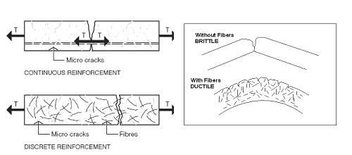
Plain, unreinforced concrete is a brittle material, with a low tensile strength and a low strain capacity. The role of randomly distributed discontinuous fibers is to bridge across the cracks that develop provides some post-cracking “ductility”. If the fiber is sufficiently strong, sufficiently bonded to material, and permit the FRC to carry significant stresses over a relatively large strain capacity in the post cracking stage. There are, of course, other (and probably cheaper) ways of increasing the strength of concrete. The real contribution of the fibers is to increase the toughness of the concrete (defined as some function of the area under the load vs. deflection curve), under any type of loading. That is, the fibers tend to increase the strain at peak load, and provide a great deal of energy absorption in post-peak portion of the load vs. deflection curve. When the fiber reinforcement is in the form of short discrete fibers, they act effectively as rigid inclusions in the concrete matrix. Physically, they have thus the same order of magnitude as aggregate inclusions; steel fiber
reinforcement cannot therefore be regarded as a direct replacement of longitudinal reinforcement in reinforced and pre-stressed structural members. However, because of the inherent material properties of fiber concrete, the presence of fibers in the body of the concrete or the provision of a tensile skin of fiber concrete can be expected to improve the resistance of conventionally reinforced structural members to cracking, deflection and other serviceability conditions. The fiber reinforcement may be used in the form of three – dimensionally randomly distributed fibers throughout the structural member when the added advantages of the fiber to shear resistance and crack control can be further utilized. On the other hand, the fiber concrete may also be used as a tensile skin to cover the steel reinforcement when a more efficient two – dimensional orientation of the fibers could be obtained.
Short steel fibers improve the tensile ability of concrete. The effect of steel fibers on the properties of SFRC depends on their orientation distribution in the concrete matrix. For this end, the research covered the development of the measuring methods with which the orientation of fibers can be defined in the hardened concrete samples.
The specimens—cuboids and cylinders–were examined employing two methods: slicing and X-Ray micro-tomography, respectively. Slicing method included two approaches: image processing and analysis and DC-conductivity testing. During the first approach the cuboids were cut into the slices and photos were taken from both sides of a slice. Further, these photos were processed and analyzed. According to the geometry of cut fibers, which was specified by fitting the ellipses, it was possible to define fiber orientations in spherical polar coordinates. DC-conductivity testing was acting as an extension of image analysis approach as it used the coordinates determined in image analysis. DC-conductivity testing is capable to measure the in-plane angle in the interval from [0, 360] degrees, which in the case of image analysis is only from [0, 180] degrees.
X-Ray Micro-Tomography method allows receiving the 3D (three-dimensional) images of scanned SFRC specimens.
‘Both methods give the reliable results and thus can be applied to determine the orientation of fibers in the real concrete samples.
It is important that the orientation of fibers is defined in spherical polar coordinates since this allows evaluation of the actual influence of fiber orientations on the mechanical properties of the composite.
The material model for SFRC is orthotropic linear-elastic and it utilizes the tensor quantities, which are independent of any reference frame. The model can be used to calculate the bearing capacity of SFRC taking into account, significantly more accurately than before, the effect of fiber orientations. The model developed is appropriate for the case of micro-cracks and can be used in numerical applications.
Ms. Eik utilized the orientation of fibers measured by the X-ray micro-tomography method to demonstrate the material model developed.
The results of the doctoral work encourage the development of manufacturing methods for SFRC. The measuring methods elaborated can allow manufactures to monitor and control the orientation of fibers. Utilizing the material model developed, it is possible to simulate the orientation of fibers and, thus, estimate the load-bearing capacity of a SFRC structure.
Composition of Concretes
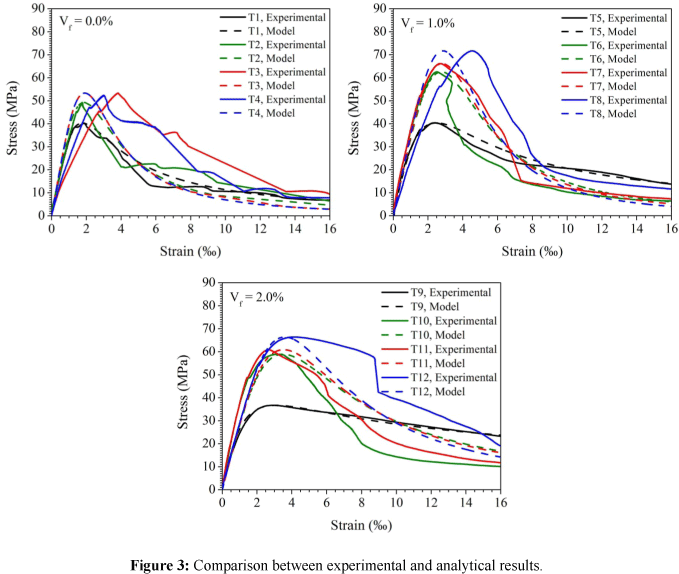
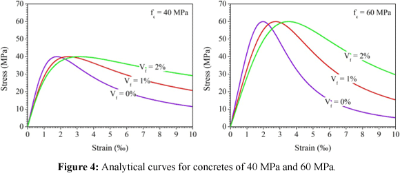
Concretes with 40 MPa were produced with Portland Cement Type CP II F 32 (OPC-Grade 43, cement with limestone filler), sand, coarse aggregate with maximum size of 12.5 mm, water and super-plasticizer admixture. To improve the workability of fresh concrete and reduce the consumption of cement, 5% of silica fume/micro-silica were added in partial replacement of cement and 20% of fly-ash as mineral addition. To these concretes steel fibers 35 mm long were added in fiber volumetric fractions of 1.0% and 2.0%, having been the fiber aspect ratio of 64. Concretes with 60 MPa were produced with the same materials, except fly-ash.
Variations of -21% (for mixture T10) and +52% (for mixture T4) in the ratio between relative toughness values obtained from experimental results and from proposed models were observed. The peak strain also presented high variations: -24% (for mixture T11) to +100% (for mixture T3). These differences between experimental and analytical values are due to the experimental curve shape on descending branch, whose behavior is affected by the high scattering intrinsic to the adding of fibers to concrete, since ascending branch was represented satisfactorily in the most cases. Values of relative toughness and peak strain with reasonable accuracy and confidence level of 90% were observed in 50% of the cases. Although the differences observed between experimental and analytical results, the model can be considered as valid.
STATIC MECHANICAL PROPERTIES
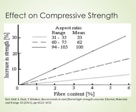
Compressive Strength Fibers do little to enhance the static compressive strength of concrete, with increases in strength ranging from essentially nil to perhaps 25%. Even in members which contain conventional reinforcement in addition to the steel fibers, the fibers have little effect on compressive strength. However, the fibers do substantially increase the post-cracking ductility, or energy absorption of the material.
This is shown graphically in the compressive stress-strain curves of SFRC in figure 3 Tensile Strength Fibers aligned in the direction of the tensile stress may bring about very large increases in direct tensile strength, as high as 133% for 5% of smooth, straight steel fibers. However, for more or less randomly distributed fibers, the increase in strength is much smaller, ranging from as little as no increase in some instances to perhaps 60%, with many investigations indicating intermediate values, as shown in figure 4. Splitting-tension test of SFRC show similar result. Thus, adding fibers merely to increase the direct tensile strength is probably not 112 worthwhile. However, as in compression, steel fibers do lead to major increases in the post cracking behavior or toughness of the composites. Figure 4 Influence of fiber content on tensile strength
Flexural Strength Steel fibers are generally found to have aggregate much greater effect on the flexural strength of SFRC than on either the compressive or tensile strength, with increases of more than 100% having been reported. The increase in flexural strength is particularly sensitive, not only to the fiber volume, but also to the aspect ratio of the fibers, with higher aspect ratio leading to larger strength increases.
Characterization along with typical properties includes:
Cross-section: ………………………… Round, flat, crescent, etc
Deformations: …………………………. Straight, wavy, end hook, etc.
Length:……………………………………19-60 mm
Aspect Ratio (length/diameter):……. 30-100
Tensile strength……………………….. 345-1700 N/mm2
Young´s modulus……………………… 205 kN/mm2
We are leading service providers for Tremix Flooring or Vacuum dewatered flooring (VDF) & IPS Flooring. Various Floors in factories, warehouses and industries has extensive application of concrete which is a versatile flooring and has been in use for a long time. To mitigate the normal issues you face with concrete, a system was devised to improve the properties of concrete floors. This system is called Vacuum Dewatered Floors (VDF) or Tremix Flooring.
In this system, concrete is poured in place & vibrated with a poker vibrator. Then a screed vibrator is run over the surface, supported on channel shuttering spaced 4.0 meters apart. The screed vibrator is run twice to achieve optimum compaction & leveling. After this a system of lower mats & top mat is laid on the green concrete & this is attached to a vacuum pump. This draws out excess water. The surface immediately hardens after this process & becomes workable. This is followed by running the mechanical power floater to level off the surface. The last process is working the power trowel to trowel off the final finished surface.
The process essentially comprises of concrete leveling by Surface Vibrators, removal of excess water with the help of Vacuum Pump and Suction Mats, and finishing the hardened concrete by Skim-Floater / Power Trowel. If applied correctly, this process gives definite advantages i.e. higher compressive strength, even finish, better joints, increased wear resistance, less curing time etc. (please refer the Product catalogue for more information). The key part in this process is the Vacuum Pump, Top Cover and Filter Pads as the performance of these determines the effectiveness of the process. Bubble shaped Filter pads gives the best results as there is always free space for water to flow. The substitutes which are commonly found on sites are made of Nylon nets and do not dewater the concrete correctly as there is no passage for water to flow. The effectiveness of dewatering can be easily seen after the dewatering is stopped. For correct dewatering, the filter pads remain clean without any slurry sticking to them and concrete surface completely dry. Another test is the dewatering time; it should be done for 1 – 1.5 minutes per centimeter thickness of concrete. Dewatering time depends on thickness and not on area being dewatered.
The reason for the popularity of this process in India is that it is semi-automatic. It came when water was the only material available for adjusting slump. Concrete was required to be produced at site by 7/10 mixers in relatively small quantity. It gave the freedom from 4 x 4 meters panels and allowed stripped construction as long as 40 meters thereby increasing daily production.
Vacuum Dewatered Flooring, also known as VDF, is a special type of Flooring Technique to achieve High Strength, Durability, Longer Life, Better Finish and Faster Work. This type of floor is suitable for high abrasion & heavy traffic movement. The Vacuum Dewatered Flooring or VDF Flooring is a system for laying high quality concrete floors where the key is Dewatering of Concrete by Vacuum Process wherein surplus water from the concrete is removed immediately after placing and vibration, thereby reducing the water: cement ratio to the optimum level. Reduced water: cement ratio automatically leads to a noticeable improvement in almost each of the concrete properties.
VDF offers a solution to the problem of combining high workability with a minimum Water / Cement Ratio in case of freshly placed concrete. This is a process where excess water that is available for the workability is extracted from a certain depth of concrete by some mechanical means. The final water / Cement ratio before the concrete sets is thus reduced and as a result, controls the strength. It also imparts higher density, lower permeability, and greater durability with higher resistance to abrasion to the concrete placed with proper care and discipline.
The Process
In this system of VDF Flooring or Vacuum Dewatered Flooring, concrete is poured in place & vibrated with a poker vibrator especially to the sides of the panel for floor thickness more than 100mm. Then surface vibration is done using double beam screed vibrator running over the surface, supported on channel shuttering spaced 4.0 meters apart. The screed vibrator is run twice to achieve optimum compaction &leveling. The vibrated surface is then leveled using a straight edge.
After this a system of lower mats & top mat is laid on the green concrete & this is attached to a vacuum pump. This draws out surplus water if any. The concrete is left to stiffen. When the base concrete has stiffened to the point when light foot traffic leaves an imprint of about 3-6 mm, Floor Hardener, if specified, is applied at this stage evenly at rate of between 3-5 Kg per sqm. Any bleed water should now have evaporated, but the concrete should have a wet sheen. The concrete is then further compacted and leveled using Power Floater followed by finishing as per the requirement using Power Trowel.
Vacuum processing improves compressive strength and how vacuum affect the top and bottom part of the slab respectively. Note that after just seven days the compressive strength value of vacuum dewatered concrete will be the same as that of normal concrete after 28 days.
Proper Care
Production of a quality concrete slab requires proper techniques and adequate planning. The following key areas have been identified as the most critical to achieving a satisfactory result.
Subgrade- The subgrade must be properly compacted and drained in order to give the bearing support assumed in design. Without support, the slab has little chance of supporting design loads. Maximum deflection under a fully loaded ready mix truck should be 13 mm.
Vapor Barriers- are normally provided to minimizemoisture transmission. The selection of vapor barrier is based on the moisture sensitivity of the floor covering to be installed. Vapor barriers can be placed directly beneath and in contact with the concrete slab, or a layer of granular fill may be installed between the concrete and the barrier. Direct placement of concrete on top of a vapor barrier can contribute to problems such as plastic and drying shrinkage cracking and curling.
Admixtures– use of suitable admixture for enhancing specific properties depending on the functionality should be carefully chosen and decided. Testing should be performed to determine how the admixture(s) will affect the properties of the concrete given the specified job materials, as well as the anticipated conditions and construction procedures. Often, admixtures are used in combination with one another. A second admixture can significantly affect the dosage requirement of both admixtures. Preliminary tests are recommended to ensure the optimum dosage of each admixture. Successful placements onsite will verify proper workability, finish ability and setting time. It is important to consult the manufacturer for specific material handling, dosage and application instructions.
Synthetic Fibers- Synthetic fibers for use in concrete floors increase the cohesiveness of concrete and should meet the requirements specified. The most widely used synthetic fibers are polypropylene and nylon, although other types are available. Fibers are generally available in both fibrillated and monofilament forms. Structural macro-fibers (larger coarse fibers) can be used to provide equivalent post-crack strength to conventional reinforcement depending on the specific fiber dosage (see page 8 of this guide for further information). Synthetic macro fibers can also be used to reduce plastic shrinkage cracks as well as minimizing drying shrinkage cracks when used in a low shrinkage mix (0.04% @ 28 days or less). Synthetic micro-fibers, polypropylene and nylon, are most widely used to reduce the formation of plastic shrinkage cracks and to hold cracks tight.
Placing Sequence- In many cases, the most efficient way to place concrete in large areas is in long alternating strips. Strip placements allow superior access to the sections being placed and most suitable in case of VDF.
Bleeding- Excessive bleeding is a major deterrent to achieving quality slab surfaces always. Though in case of VDF this is taken care of by the very process, care should be taken in respect of proper concrete mix proportioning, the use of a well graded aggregate, controlled vibration and slump, concrete temperature control help. Collected bleed water should be removed before the start of finishing operations or the application of dry shake surface hardeners or toppings.
Evaporation-Rapid evaporation and moisture loss can result in plastic shrinkage cracking in the slab surface. This undesirable appearance can be minimized or prevented by dampening the subgrade, cooling water and aggregates, using windbreaks or sunshades, eliminating vapour barriers, using fog sprays, and/or treating the concrete with a monomolecular film just after floating.
Typical Application Areas
- Warehouses, Store houses, Factories
- Roads, Sports Courts
- Cellars, Parking Areas
- Manufacturing Areas,
- As the base floor for special finish Floorings
Benefits & Features
- Increased Compressive strength by up to 60%
- Reduced Cement consumption by 40% as no cement is required separately for finishing.
- Increased Abrasion resistance by @ 60%
- Reduced Shrinkage.
- Minimizing dusting, crack formation
- Uniform homogeneous floor with High flatness accuracy
- Increased wear resistance
- Earlier utilization and Reduced maintenance cost
- Lower water permeability due to increased density.
- Minimizes dry shrinkage and plastic shrinkage
- Controlled working Cycle
- Earlier start of finishing operation
- Fewer forms faster reutilization
- High early strength minimizes damage on newly cast floors
Procedure
- Clean the location free from dust and other unwanted material. If required floor wash to be carried out to ensure proper bonding between the concrete and the surface to receive the concrete.
- Provide a suitable type of Vapor Barrier if required as per specification.
- Mark the area longitudinally so as to place the end channels at a spacing not to exceed 4 meters.
- Provide Reinforcement (Mesh or In-situ fabrication) with provision for dowel bars. These dowel bars are required as alternate panels are cast.
- Place end channels at about 4 meters apart, well anchored avoiding any movement.
- Place Concrete as per the design mix preferably through a transit mixer.
- Spread and Compact properly using needle vibrators.
- Run the screed vibrator spanned across the two end channels twice (Figure 3). Double Beam Screed Vibrator- used for leveling as well as compaction of green concrete it consists of high quality steel bar (4.2meter) with of 250 spacing MM in between. Our special water protective vibrator motor is mounted in the centre which produces 1830 N centrifugal force which is most ideal for compaction of green concrete. These vibrators are also available in different sizes from 2 meter to 5.5 meter.
- Spread the Vacuum mat system. The vacuum is applied through porous mats connected to a vacuum pump. The mats are placed on fine filter pads which are provided to prevent the removal of cement together with the water. The mats can be placed on the concrete immediately after screeding, and can also be incorporated in the inside faces of vertical forms. The vacuum applied is normally of the magnitude 0.08 MPa. This vacuum reduces the water content usually by about 20%. The reduction is greater near to the mat. Care should be taken proper trained staff operates and applies the correct pressure.
- Vacuum pressure is applied, it compress the concrete sufficiently so that it is necessary to place extra concrete to compensate. Usually the slab gets compressed about 2 percent. This means that for a 6-inch-thick slab the screeds must be set high by 1/8 inch.
- Suction Mat & Top Mat, which is the most important part of the vacuum de watering system. Suction mat is also known as the Filter Mat and comprises of a filter cloth on a wire mesh. The filter mat ensures that the cement fines are not sucked at the time of the vacuum process. These are available in size of 35 sq meters total. The top mat is only placed on top of the filter and work for sealing the vacuum.
- Extract excess water from concrete using vacuum pump-Vacuum pump, Filter mat and Top mat are important components in the VDF process. They help to extract the excess water as described above from the concrete matrix. The excess water thus sucked is diverted ensuring not to get remixed with the concrete that is already placed.
- Allow concrete to initially set. Start finishing operation using mechanical floaters. (Figure 6)- Power Trowel that is surface finishing equipment that polishes the surface after floating operation and 3 to 4 passes are required for giving fine finish to the floor. Power Floater, which is surface grinding equipment powered by 3 H.P. Electric motor through gear box with floating RPM of 130. The Power Floater offered by us grinds the surface to make it wear resistance.
- Edges to be finished manually or using smaller discs.
- Avoid damage to the finished floor.
- Cure the concrete
- Cut the groves as specified and fill the sealant.
The Operation
• In order to obtain a high quality concrete floor using this method, it is essential to follow the various operations in the correct sequence. Initially, poker vibration is essential, especially at the panel edges. This results in proper compaction of the concrete and hence elimination of voids and entrapped air.
• Poker vibration never really gives a leveled surface. It is therefore essential to combine this vibration with surface vibration (screeding), in order to obtain a vibrated concrete with a leveled surface. Two passes with surface vibrator are normally recommended.
• The Surface Vibrator is guided by two men, standing on either side of the panel. Vacuum dewatering process removes surplus water always present in the concrete. This is done using the Vacuum Equipment comprising of Suction Mat Top Cover, Filter pads and Vacuum Pump. The process starts immediately after surface vibration.
• Filter pads are placed on the fresh concrete leaving about 4 inches of fresh concrete exposed on all sides. The Top Cover is then placed on the filter pads and rolled out till it covers the strips of exposed concrete on all sides. The Top Cover is then connected to the vacuum pump through a suction hose and the pump is started.
• Vacuum is immediately created between the filter pads and the top cover. Atmospheric pressure compresses the concrete and the surplus water is squeezed out. This process lowers the water content in the concrete by 15-25%.
• The dewatering operation takes approximately 1.5 – 2 minutes per centimetre thickness of the floor. The dewatered concrete is compacted and dried to such an extent that it is possible to walk on it without leaving any foot prints. This is the indication of concrete being properly dewatered and ready for finishing.
• The finishing operations – Floating & Trowelling take place right after dewatering. Floating operation is done with Floating disc. This ensures after mixing of sand & cement particles, further compaction and closing the pores on the surface. Floating operation generates skid-free finish.
• Trowelling is done with Trowelling blades in order to further improve the wear resistance, minimize dusting and obtain smoother finish. Repeated passes with disc and blades improve the wear resistance substantially.
Factors affecting VDF
Fresh concrete contains a system of water filled channels and the application of a vacuum to the fresh concrete surface results in water being extracted from a certain depth of the concrete, especially near to the top surface. This water is referred to as ‘water of workability’. The final water / cement ratio at the surface is thus reduced and as this ratio largely controls the strength of the concrete and a higher strength will be obtained. However it must be noted that some of the water extracted leaves voids and as such the theoretical advantage of removing the water may not be fully achieved in practice. It is also observed in practice that if Vacuum Dewatering process is applied over a 25 minute period, it can reduce the water content by 20% but is only really effective at depths of 100 – 150mm.
Although there are several advantages using Vacuum Dewatering process on concrete floors resulting in increased strengths, increased density and assists increase abrasion resistance, there are some factors that affect the the entire process. However, while designing an effective VDF, following factors are to be considered.
- The withdrawal of water produces settlement of the concrete, possibly up to 3%. This can be topped up with the application of a dry shake but with little bleed water at the surface there is a risk of subsequent delamination.
- In practice the VDF process produces voids in the concrete and it has been found that with the same water / cement ratio, ordinary concrete has been found to have a somewhat higher strength than VDF concrete.
- VDF concrete stiffens very quickly. This is acceptable in cold climatic conditions but leaves the window of workability very short in hotter climates.
- Some of the finer materials are removed with the VDF process and fine sands and cement contents of greater than 350 Kg / m should be avoided.
Groove Cutting
Concrete expands and contracts constantly with changes in the temperature, the moisture content of the air and due to drying of cement which results in shrinkage.? The movements result in stress that can cause cracks in the concrete and destabilization of the base.
Uncontrolled cracking can cause an uneven surface, which is subject to increased wear over time and water seepage, which can damage the substrate. ?Though cracking is almost impossible to prevent, it can be controlled.? The use of specific types of control joints helps accommodate the movement of the concrete and avoid long-term damage.
Groove Cutting is cutting the laid concrete providing grooves of required size within 48 hours of placing of the concrete to form bays of 4Mtrs X 4Mtrs using heavy duty cutting machine with diamond cutting wheel and filling of the grooves with appropriate sealant.?
Making Grooves is one such method to insert contraction joints into slabs to guide cracks along a predetermined line. The purpose of the Groove Cutting is to weaken the slab along the approved line so that the slab cracks there instead of somewhere else. In order to be effective, the contraction joint must be at least one quarter as deep as the slab is thick.
In case of heavy load traffic, a Load Transfer mechanism is used. Load transfer devices prevent the cement slabs from shifting under heavy loads. Shifting can cause uneven slabs and breakdown in the joints. Dowels, load plates, or slots can be embedded into the concrete to act as load transfer devices. These devices are laid perpendicular to the construction joint, extending into both slabs across the joint. Their purpose is to distribute the load evenly between slabs thereby protecting the concrete along the joints.
Joint Sealants
Joint Fillers and Sealants are hard, semi-rigid materials typically used to fill the construction joints in concrete floors. The joint filler transfers the load of heavy wheeled traffic across the joint, protecting the joint edges from damage.
Joint sealants are flexible materials that expand and contract along with the concrete. Their main purpose is to prevent water, other liquids, and debris from entering the joint. They can also improve the appearance of a floor. Most sealants are available in colours and can make the joints “disappear”. Sealants are one or two-component polyurethanes and should not be used on floors that will receive heavy traffic or loads because sealants will not support and protect the joint edges.
Dry shake floor hardeners come in mineral aggregate and metallic varieties. The selection of a dry shake hardener is dependent on the specific solution intended for the particular application. Floor hardeners provide a dense, tough surface capable of withstanding the abrasion and impact loading seen by floor slabs in a wide range of commercial, industrial and manufacturing facilities. Dry shake hardeners provide 2 to 8 times the abrasion resistance of plain, cured concrete. Most manufacturers offer hardeners in a range of colors.
Special Finishes
Metallic floor hardeners are formulated with graded, non-oxidizing or oxidizing metallic aggregate in a high strength cementitious binder. Mineral hardeners contain a mixture of well graded, non-metallic aggregates, plasticizer and cement binder. Both are recommended for use in either interior or exterior applications where a hard, long wearing, heavy duty floor is required. Metallic hardeners should not be applied to concrete with intentionally added chloride.
Non-oxidizing metallic and mineral aggregates come in a light reflective version designed to increase reflectivity to improve lighting levels. In combination with providing increased abrasion resistance, this type of dry shake floor hardener can boost reflectivity in excess of 60%. Benefits can include lower electrical requirements and fewer light fixtures resulting in significant cost savings.
The use of embedded mineral or metallic hardeners is usually intended for industrial floors exposed to moderate or heavy traffic. In some cases, floor hardeners are applied where impact resistance is required. The manufacturer’s recommendations should be followed along with the procedures.
Accordingly, dry shake floor hardeners should be embedded near the top surface of the slab to obtain the required surface hardness, toughness and impact resistance. It is recommended that the total air content of normal weight concrete should not exceed 3% except when service conditions expose the concrete to freeze/thaw cycling and the slab is not hard-trowel finished. Consult the manufacturer and ACI for specific installation guidelines since these vary slightly between metallic and mineral hardeners due to differences in their properties. In general, it is advised that good construction practices be followed. This includes obtaining flat and level surfaces and joints, using proposed mix proportions when installing test panels or placements and making any required adjustments at that time. A concrete mix design review should be conducted prior to installation of a dry shake floor hardener with all appropriate parties present. Issues such as air content, use of blended cements, concrete admixtures, and placing and finishing techniques should be discussed and agreed upon before the project begins.
